Search the whole station Products News
functional testing
Project Case
With the rapid development of the automobile industry in the direction of intelligence and electrification, as a key component to ensure driving safety and enhance the sense of technology of vehicles, the reliability of its driving board is very important. This test scheme takes LabView, which is powerful and flexible, as the core control platform, and aims to build a comprehensive and accurate functional test system for PTI automobile headlight driving board.
Automatic learning of network code
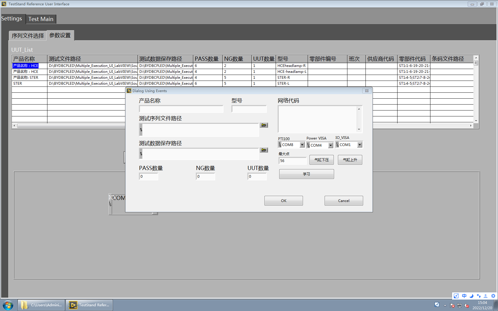
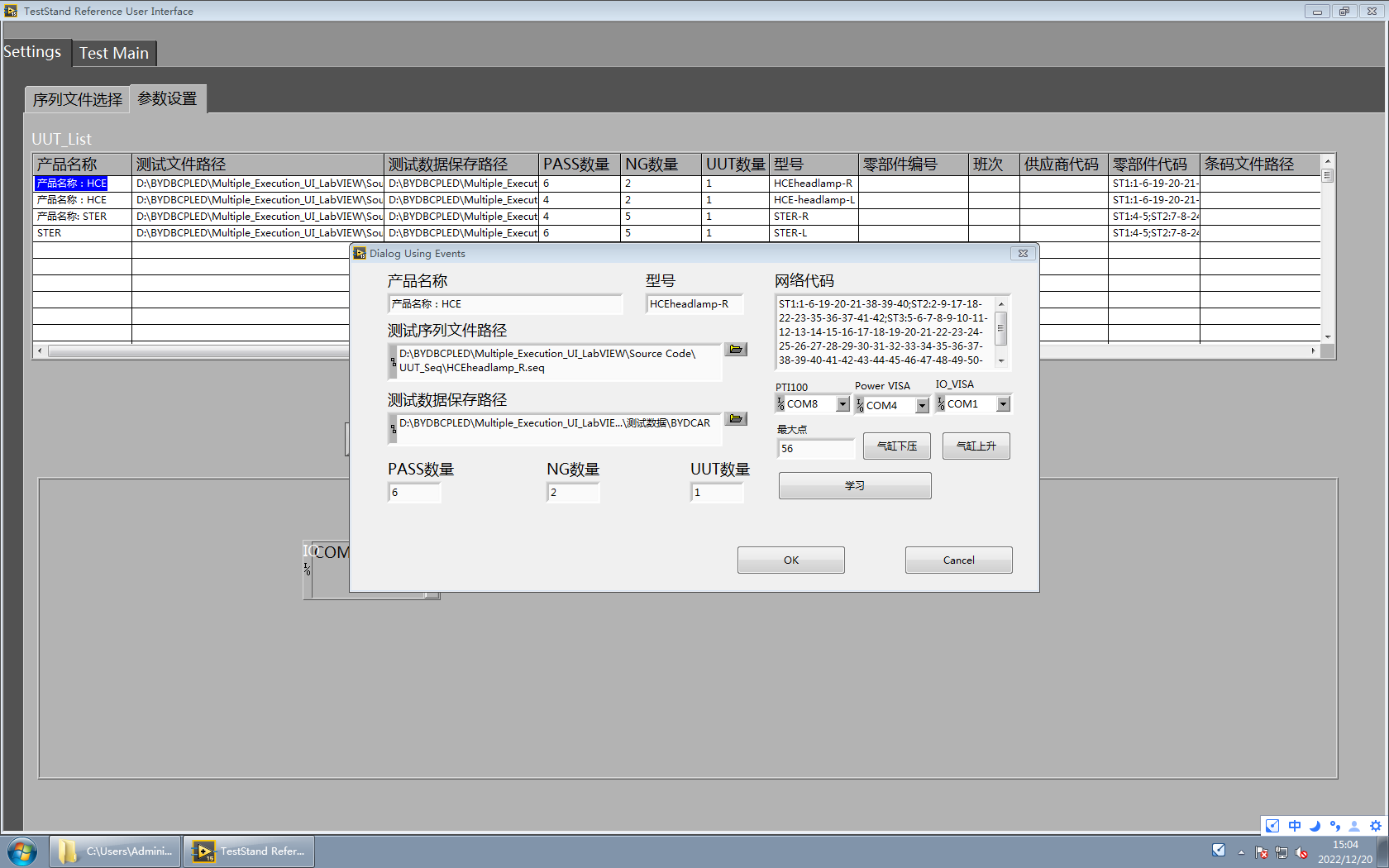
Before the test process is started, users can click “Create” to edit key parameters such as product name, model and test data saving path in the operation interface, and these parameters will be permanently saved once they are set. When entering the test link, place the circuit board to be tested on the press, then click the cylinder to press it down, and click the learn button when it is pressed to the specified position. After a short wait, the program can accurately read the unique network code of the circuit board under test with the help of hardware, and since then PTI100 has established a one-to-one mapping relationship between the code and the model of the board under test. Relying on this correlation, the system can not only detect the voltage between any two points of the circuit board, but also the subsequent software can automatically carry out a series of related tests such as open-short circuit and voltage test according to the read network code, and generate the relevant information generated during the test in the corresponding report according to the established format, which greatly facilitates the inquiry and traceability and provides strong data support for product quality control.

Edit key parameters such as product name, model number and storage path of test data.

The program accurately reads the unique network code of the circuit board to be tested with the help of hardware.
Fixture sharing
Pass/Fail test function
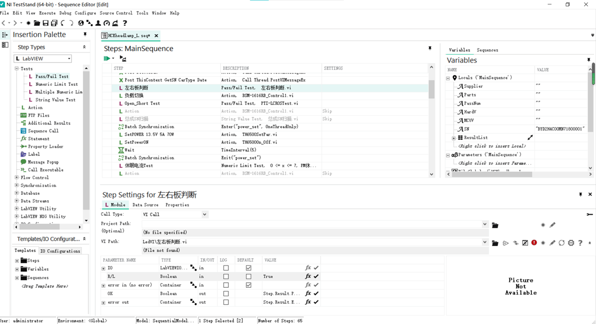
In the project, the left and right circuit boards are completely identical in appearance, but the colors are different. By adding color sensors, the left and right boards correspond to the preset colors, and comparing with the program to see whether the operation of the wrong selection program occurs, combined with the Pass/Fail test action, the fixture sharing is realized, and the operator’s wrong selection is effectively prevented.
As shown in the figure, create a new test action, import sub-VI, and select True at the R/L checkbox, that is, the test is deemed to have passed after receiving the True signal from the hardware side.
There are related voltage measurement modules in the PTI100 test system, which can measure all the loads that need to be measured one by one through specific circuit connection and measurement algorithm. During the measurement, the system will automatically control the measurement range, precision and sampling frequency according to the preset procedures and parameters to ensure the accuracy and reliability of the measurement results.
The test passes, the interface shows passed, the green light is on, and the solenoid valve automatically rises. If the test fails, the interface displays failed, the red light is on, and the alarm sounds. Press the up key to raise the solenoid valve, and the alarm is cancelled. During the test, the data report of each test item will be automatically generated, including the actual test value, the set upper and lower limits, and whether it is qualified or not. The report can be viewed by clicking on the data panel or opened in a preset folder.
Equipment shot
 0
0

